|
Water
Softening
Water,
passing through the atmosphere as snow or rain, picks
up carbon dioxide (CO2) and other
acid gases and reaches the Earth’s surface as a
weakly acidic solution (CO2 + H2O
-> H2CO3)
commonly referred to as carbonic acid.. The rain that
falls into surface waters such as streams, rivers, ponds
and lakes are normally low in dissolved solids and hardness.
As
this water soaks in, it passes through various strata
containing limestone (CaCO3) which
neutralizes the acid forming a soluble calcium bicarbonate
salt (H2CO3
+ CaCO3 -> Ca (HCO3)2
which then dissociates into ions. (Ca++) ions with a plus
2 positive charge is a cation and HCO3
- with a single negative charge contributes two anions.
This is how calcium (and magnesium) end up in all our
water supplies. Where the calcium and magnesium content
is high these waters are described as “hard”
waters.
When
hard water is heated, the Ca(HCO3)2
decomposes to CaCO3 and evolves
CO2 gas and H2O
(water). CaCO3 is insoluble and
deposits on the surfaces of water heaters, often found
in boilers, coffee makers, pipes and on to fabrics, creating
a hard scale (known as calcite, lime scale, boiler scale
or hardness scale). This scale is a poor conductor of
heat and so it takes more energy to heat water if the
heater element or boiler tube is covered with this scale.
Scale can also clog pipes and appliances and reduces the
life of fabrics due to its abrasive nature. In addition,
when washing you will notice the soluble calcium and magnesium
salts will react with soap causing the familiar bathtub
ring and soap scum. Needless to say, it is often desirable
to remove hardness ions before using the water in residential
as well as industrial applications.
Ion
exchange is often the process of choice for removing hardness
ions. In domestic applications a low level of hardness
can be permitted. In industrial applications, particularly
boilers, total hardness has to be almost totally removed.
Ion
exchange was first observed and recognized by Thompson
and Way in 1858 noting that when an ammonium salt was
poured through soil, a different water composition trickled
out of the bottom of the container. The soil had captured
the ammonium ion and released sodium. Natural soil contains
clays and zeolites that have ion exchange capabilities.
By order of selectivity, multi-valent ions are grabbed
onto by ion exchangers which will then release a less
tightly held ion (which is often more desirable). It should
be noted that mono-valent ions such as sodium or potassium
do not cause scale and do not react with soap.
Zeolites
were synthesized in 1903 offering higher capacity and
stability than the natural zeolites and German industrial
pioneer, Robert Gans commercialized the first regenerable
ion exchanger for removing hardness in 1905.
The
synthesis of new chemistry gradually improved the efficiency
of the regenerable softener through the 1940s when G.F.
D’Alelio of GE produced the first suspension polymers
of styrene and di-vinyl benzene (S/DVB) which gave birth
to the modern ion exchanger. The basic chemistry of softening
resins has remained unchanged since that time. Ion exchange
softening systems use reactive plastic polymer beads with
chemical functionality that selectively captures the di-valent
ions such as calcium and magnesium and releases less tightly
held monovalent ions, normally sodium. The reaction is
as follows:
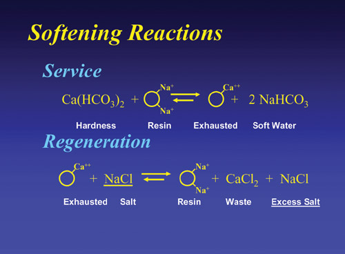
The
-> <- means that there is equilibrium between the
water composition and the amount of hardness that can
be removed. It also means that the reaction is reversible
should there be a high driving force applied to the exhausted
resin. If that driving force is a concentrated brine (NaCl
or KCl), the hardness on the expended resin is driven
off and the mono-valent sodium or potassium takes its
place.
This
is called “regeneration”. So a softener system,
consisting of resin beads in a bed that has the ability
to pick up hardness by ion exchange (hardness exchanged
for “softness” ) and then be regenerated by
a high concentration (10% brine) of salt and have its
capacity restored. The system can be used over and over
and lasts for years.
Water
hardness is usually commonly reported in ppm (parts per
million) or mg/l (milligrams per litre as CaCO3
(calcium carbonate) and fortunately 1 ppm = 1 mg/l.
The
term CaCO3 defines a convention
representing the number of ions to be exchanged. The water
analysis is usually presented in mg/l (as the ion) which
has to be converted to mg/l as CaCO3
using conversion factors.
The
factor for Ca++ is 2.5. You then multiply the mg/l as
Ca++ by 2.5 to get mg/l as CaCO3.
For Mg++, the factor is 4.1. Once you have the calcium
and magnesium as CaCO3 calculated
you add them to get total hardness (as CaCO3).
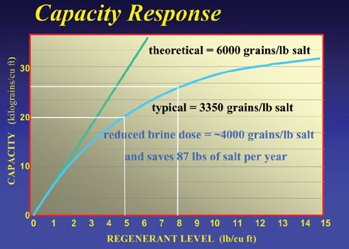
The
capacity of the resin, which will vary depending upon
the salt dose per cubic foot of resin and can be approximated
from the following table:
Regen
Level g/l (NaCl) |
Regen
Level lbs (NaCl) |
Capacity
(g/l) |
Capacity
(Kgs/cf3) |
65 |
4 |
42 |
18 |
96 |
6 |
48 |
21 |
128 |
8 |
55 |
24 |
160 |
10 |
60 |
27 |
190 |
12 |
66 |
29 |
240 |
15 |
70 |
30 |
Once
you have the capacity in g/l or ft3, multiply that number
by the number of liters or cubic feet of resin in the
system to get system capacity. Then divide that number
in by the amount of hardness in the water supply in mg/l
as CaCO3 and this will indicate
the amount of water that can approximately be treated
between regenerations in m3 (x 1000 to get volume of water
in litres).
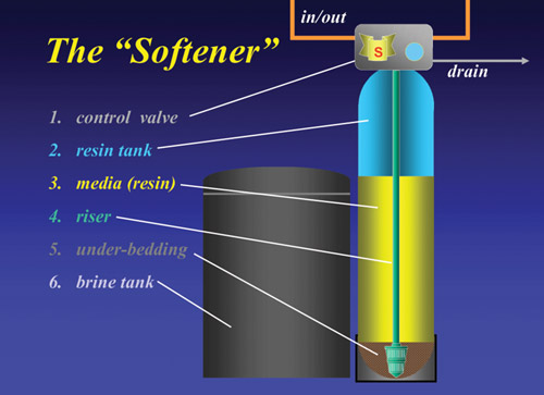
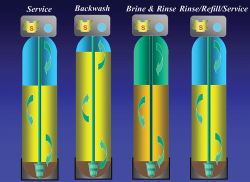
The
basic softener consists of an exchange resin in a tank
with a control valve (to control the regeneration cycles)
and a brine source. Typically, it would look like this:
There
are many factors controlling how well your softener works.
One is the water composition. The higher the Ca and Mg
of the raw water, the fewer gallons your system will produce
between regenerations (cleanings). The more salt you use
per regeneration, the better the performance (in terms
of percentage of hardness removed) and capacity (how much
it will treat). Typically, a 15 liter (1 cubic foot) unit
regenerating with 160 g/l (8 lbs) of salt will produce
4500 liters (2100 gallons) of treated water with a feed
of 200 mg/l (10 gpm) hardness.
Regeneration
is generally initiated by a time clock, gallons meter
or an electronic sensor. During regeneration, the service
water may bypass the treatment system giving a hard water
effluent. To avoid this, industrial systems are designed
with a twin alternating operation mode using two systems.
The
first step in regeneration is to backwash the system by
running water backwards through the bottom of the bed.
This lifts the bed and dislodges dirt and debris. The
bed is then settled and regenerated with a 10% salt solution.
This step drives off the hardness and restores capacity.
The bed is then rinsed and returned to service. The total
time to regenerate is <2 hours and the total water
used is about 7 x the resin volume: 15 litre bed = 105
litres (50 gal per ft3). The wastewater is discharged
to the sewer or septic system.
For
a typical home use, a 15 liter (1 ft3) softener will serve
most needs of a small home. If the water is very high
in total harness, (> 250 mg/l) (>25 gpm) or the
family is large then a larger systems may be needed. Commercial
and industrial systems are usually sized to produce a
certain run length—say 8 hours. With a feed harness
of 200 mg/l (12 gpm) and a flow of 10 m3/h (25 gpm), the
challenge is (200 x 10 / 1000 = 2 Kg load per hour) (12
x 25 x 60 min/hr = 18,000 grains per hour) and if the
run length needed is 8 hours (2 x 8 = 16 Kg)(18,000 x
8 = 144,000) you divide the load (16 Kg) (144Kgr) by the
capacity (say 50 g/l)(22 Krg) and we see that we would
need 0.32 m3 (320 liters) (6.55 ft3) resin volume in the
softener.
At
10 m3/h (25 gpm) , the relative flow rate would be (10/0.32
= 31.25 BV/h) (25/6.55 = 3.8 gpm/ft3) This flow is generally
considered acceptable for residential and commercial needs
but critical applications (high pressure boilers) might
choose to have a larger system with 650 litres (1 –
3 gpm/ft3) on a operating 12 – 24 hour cycle. Residential
systems often operate intermittently at flow rates of
up to 80 BV/h (bed volume per hour) (10 gpm/ft3) of resin.
Typical flows are much lower (average is closer to 20-30
BV/h) (2.5 gpm). As a result of higher flow peaks and
the need to minimize brine usage lower regeneration levels
are now being employed (120 g/l or less) (8 lbs/ft3),
residential systems generally experience higher levels
of hardness in the effluent but still less than 20 mg/l
(1 gpg (17ppm)).
When
a resin system regenerates, only about 60% of the total
capacity is restored. Some hardness is left on the resin.
When next in service, some of this residual harness leaches
off the resin creating a slight amount of hardness in
the effluent. This is called “leakage”. The
level of leakage is determined in part, by the total amount
of salt used to regenerate. Systems requiring very low
leakages (<1 mg/l) (<1 ppm) may require high doses
of salt (200 g/l or greater) (20 lbs/ft3).
Leakage
is the primary factor in determining the system design.
For any given water analysis, a given quality (leakage)
is produced by a given salt dose (g/l) (lbs/ft3). The
product engineering notes determine this. Once the salt
dose (for the quality needed) is determined, the capacity
is set and the system design can be initiated.
Although
synthetic resins are very durable, they are subject to
degradation due to oxidation and over time. Chlorine and
any other oxidants are detrimental. Levels of 0.5 mg/l
(0.5 ppm) have little affect on resin life but at higher
levels the life of the resin can reduce dramatically.
Also the presence of metal ions such as iron (which is
common) or copper in the feed water will foul the resin
and promote oxidative breakdown and shorten the life further.
The
basics of ion exchangers have been chemically unchanged
for more than 60 years. However, much has been done to
improve the efficiency by modifying the bead structure.
Normal beads range in particle size from 0.3 to 1.2 mm.
This is called “standard Gaussian distribution.
This mix gives good capacity and minimal pressure loss.
Most of what has been written about softening pertains
to this particle size distribution. The efficiency of
softening resins has been improved by newer manufacturing
techniques which are capable of producing beads that are
more uniform in size. Uniform bead products such as Purolite
PFC100E and PPC100 and PFC100 produce systems with lower
pressure drops and better brine efficiencies (up to 10
to 15% over the standard beads). Finer mesh (0.2 to 0.4
mm) beads have also been introduced by Purolite. These
small narrow grade resins are kinetically faster. Using
fine mesh resin such as Purolite C100EFM allows systems
that are smaller in size with higher capacity and better
brine efficiency (a gain of about 10% can be realized).
The latest development is the SST bead (Shallow Shell
Technology beads manufactured exclusively by Purolite
primarily for the USA market) which are not fully functionalized
by depth. This gives the performance of both fine mesh
and uniform particle size resins while producing higher
capacity and lower leakages than any other bead forms
at any given salt level.
With
the uniform bead, fine mesh bead and SST bead products
the enhanced performance comes from reduced diffusion
paths which are critical during the regeneration step
when the large calcium and magnesium ions have to migrate
to the surface of the bead while the resin is in contact
with the brine solution. Calcium and Magnesium ions migrate
slowly and hence a reduction in the diffusion path results
in easier and better regeneration giving rise to better
performance and higher working capacity.
In designing industrial plant consideration should be
given for proper hydraulic flow rates. Both thesuperficial
flow (flow in m3/m2/h) and volumetric flow (flow in BV/h
of resin) need to be fully considered in the design. Surface
flows should be between 10 - 40 m3/m2/h and volumetric
flows should be between 8 – 40 BV/h. Peak flow can
go up to 60 BV/h if designed correctly. Residential systems
generally operate on the upper end of good design while
major industrial systems trend towards the lower and more
conservative end.
|